
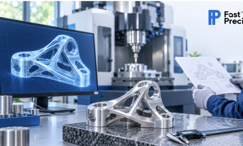
Part design is now completed in minutes by AI design tools. Engineers program load, mounting points, and weight targets, and the software provides organic shapes that appear perfectly good for the screen.
A screen will not cut metal. There are physical rules into which a machine fits and into which every machine fits—rules that no algorithm can go. Most of the parts created using AI fail during this transition.
This article will detail the troubled hot spots of the shop floor, AI geometry’s nemesis, as well as how engineers can solve the problem.
Why AI-Generated Geometry Often Fails at the Machine
Generative design programs seek out the optimum shape for a given set of objectives. Typically, the goals involve achieving stiffness, weight, and stress limits. There is nothing by default in the pricing of the manufacturing cost and access to the tools to keep track of.
The outcome is efficient but has a racy behavior when actually running in production. According to sources in the industry, design matters 70-80% of the time in the final bill of manufacturing materials. Exposing those costly decisions to an AI model that doesn’t understand how things are manufactured makes this seem like a no-brainer.
Optimization Goals Differ From Machining Goals
It is a scenario where an AI model benefits one part by carrying loads with less material. Machinists praise a part if it is reachable, stable, and repeatable. Pursuing these two objectives can sometimes work against each other.
A light lattice, such as, for instance, a Velcro surface, will save grams but will retain tools outside the cavity. The part meets simulation testing requirements, but not the requirements to obtain a quote.
Process Assumptions Hide Inside the Software
A large number of generative tools have developed as a result of additive manufacturing. Whilst other types of 3D printer schemes form structures one layer at a time, internal channels and curved ribs are near-zero cost. The CNC mill removes material from a solid part, which means that tool accessibility is crucial and all features must be accessible to a spinning tool.
This gap is usually found too late when engineers select the process from the list set up when they created the shape.
What Machinists Check First on an AI-Designed Part
Shop engineers review AI geometry against a short, predictable list. Each item below decides whether a part moves to production or returns for redesign.
- Tool access: The cutter must reach every surface from at least one approach direction.
- Internal corner radii: Every inside corner needs a radius that a standard end mill can cut.
- Wall thickness: Thin walls vibrate under cutting force and lose dimensional accuracy.
- Pocket depth to width ratio: Deep, narrow cavities force long tools that bend and chatter.
- Number of setups: Each re-clamp adds cost and alignment error.
- Tolerance and datum strategy: Critical surfaces need stable reference points the machinist can measure.
- Material choice: Titanium and stainless steel demand stiffer setups than aluminum.
Features That Break Most Often
Repeating patterns provide AI with a way to shape failures. When running a project, engineers who are familiar with these patterns can remedy them before the quote stage.
Internal Corners and Tool Reach
A milling cutter is round; therefore, it can’t be used to make a sharp inside corner. With a 6 mm end mill, there will be a minimum radius of 3 mm into each pocket. Often, near-sharp corners end up being generated by the AI model since there is no harm in deviating from sharpness with the optimizer.
There are now two poor options from which a shop must choose. It can use a small one that is slow, fragile, and breaks easily—or it can return the part. Engineers are unaware of these two, fixing a minimum internal radius at the end of the generative study.
Undercuts and Internal Cavities
Under cuts and enclosed voids are not possible with standard 3-axis milling. These features are common for generative studies, as internal hollow and curvy features are efficient load bearers.
If a machinist can’t get his fingers on it, he can’t cut it. The designers have to either eliminate the feature, break the part down into assemblies, or transfer the feature to a different process.
Thin Walls and Organic Surfaces
Testing the part on a simulator and running it through an optimizer eliminates all the grams that the simulation indicates should be eliminated. This sometimes means the thinness of walls, which a machine cannot hold steady. Thin walls bend when cut; they may not be even and may drift off-set.
There’s the problem of free-form surfaces, too. They need long, uninterrupted toolpaths and fine finishing passes, which increase cycle time.
Mating Surfaces and Tolerances
An algorithm preserves the region where two parts meet, but it does not apply fits, finishes, or tolerance classes. Engineers must add those requirements after generation. Choosing the right stock, tolerance, and finishing route matters here, and a guide on material and process considerations for custom machined parts helps teams make those calls before they release a drawing.
How Hybrid and 5-Axis Workflows Close the Gap
Some AI shapes need more than a basic mill. Two approaches make them achievable.
5-axis machining for complex components lets the cutter approach the part from many angles in a single setup. This reduces re-clamping, reaches angled features, and keeps tight relationships between surfaces. It does not remove every limit. Tool length, collision risk, and programming time still apply, and the cost per hour rises.
Hybrid workflow is printing the near-net shape first, and critical surfaces are then machined. Not very suitable for the sealing faces or bearing seats; the Ra of as-printed metal surfaces is usually 10 to 25 micrometers. Designers need to add between 0.5 and 1 mm of machining stock to those surfaces so that the CNC step will clean the surface up for the designer.
How to Prepare AI Geometry for Manufacturing
Engineers fix most problems by changing the order of work. They choose the process first, and the majority of problems can be solved by altering the sequence of work performed by engineers. They select what process they wish to use first and then create the second shape.
Begin by determining all directions of approach to the part by tools. Adjust the minimum values of the inner radius and minimum thickness of the wall. Identify surfaces that have closely specified tolerances to keep in the software.
Then, conduct a manufacturability review prior to making the file available for release. Examine the model to look for corners, pockets, or features that may be hard to reach. During the process of five or 10 minutes of review, days of quote revisions may be saved.
Last but not least, embrace some suboptimal optimization. Generally speaking, the five percent heavier component purchased in a setup will line up with the jaws and will cost a lot less than it will cost to get the perfect shape to line up, five times over.
Frequently Asked Questions
Can AI design parts for CNC machining?
Yes. There are a variety of generative CAD tools available in a few CAD platforms for 3- and 5-axis machines. Engineers need to explicitly set them: default settings are unlikely to consider them.
Can every AI-generated part be manufactured?
No. There are some shapes that have a thin wall or closed cavity or undecuts that cannot be created by standard machining processes. These areas should be re-designed or redesigned using another method like metal 3D-printing.
What is generative design in manufacturing?
Generative design is an iterative process that generates many design options from design goals and constraints and is software-driven. Engineers select the one that is most suitable for performance and production specifications.
Why do AI-designed parts need a DFM review?
The best part of AI optimizers is that they come with performance without relying on access to tools. A design-for-manufacturing review identifies sharp corners, thin walls, and unreachable features that could result in quote delays.
Can 3D printing make AI-designed parts instead?
Usually yes, as printing is additive and complex internal geometry can be done. However, in most cases, printed surfaces must go through CNC finishing to achieve tight tolerances.
Conclusion
AI can design complex parts, and it will keep improving at it. Manufacturing remains the deciding step. A shape has value only when a machine can produce it at a fair cost and a stable tolerance.
Engineers who add machining limits at the start of the study get shapes that work. Engineers who add them at the end get redesigns.
The strongest results come from teams that combine AI speed with shop-floor knowledge. Treat the machinist as a design partner, and AI geometry moves from screen to finished part with far less friction.