



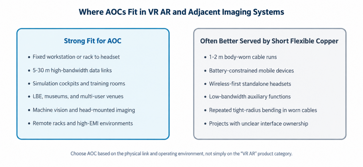
Elike’s vertical-market study covers 41 target customers, including 18 identified as near-term priority accounts, and maps 125 qualified application scenarios across seven regions. The findings support a selective market strategy: prioritize professional systems with fixed endpoints, long cable runs, and clear maintenance requirements. For short, body-worn connections, however, ultra-flexible copper or wireless architectures may be more appropriate; an AOC should not be selected simply for the sake of using optical transmission.
1. Scope and Positioning
This paper examines active optical cables and hybrid optical-electrical cable assemblies for professional VR and AR, simulation and training, and adjacent imaging systems. It covers interconnections among workstations, equipment racks, link boxes, head-mounted displays, industrial cameras, video walls, and training consoles. The examples do not imply universal compatibility with any third-party product. Nor does an AOC alone guarantee system safety, regulatory compliance, or user experience.
2. Why Professional XR Still Needs Wired Connectivity
Professional immersive systems typically demand predictable image quality, stable tracking, centralized GPU processing, secure on-premises data handling, serviceability, and predictable continuous runtime. Even as standalone and wireless headsets improve, these requirements can still make a wired architecture the stronger engineering choice. Public product documentation illustrates this design space: the Varjo XR-4 supports replaceable 5 m and 15 m display/data cable pairs; the VIVE Pro 2 uses a Link Box for DisplayPort, USB 3.0, and power; and Pimax has offered a 6 m fiber-optic cable with a stated maximum data rate of 32.4 Gbit/s.
VESA specifies a per-lane rate of 8.1 Gbit/s for DisplayPort HBR3, producing an aggregate rate of 32.4 Gbit/s across four lanes. After transport overhead, 25.92 Gbit/s is available for uncompressed video data. Actual system feasibility still depends on resolution, refresh rate, color format, compression method, protocol version, lane count, and implementation margin.
3. Application Fit Decision Framework
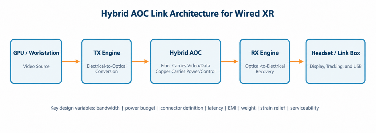
| Evaluation Question | Strong Indicators for AOC | Use with Caution or Consider Alternatives |
|---|---|---|
| Transmission distance | 5-30 m between fixed endpoints | 1-2 m at the body-worn end |
| Data path | High-speed DP, HDMI, USB 3, or 10GigE-class signals | Low-speed control or charging only |
| Operating environment | Equipment racks, simulators, venues, industrial cabinets, or high EMI | Battery-constrained or wireless-first devices |
| Service model | Replaceable cables, link boxes, or controlled installations | Sealed consumer accessories with unclear interface ownership |
| Mechanical requirements | Low mass over long distances, latching, routing, and field service | Continuous small-radius bending at the body-worn end |
| Validation basis | Customer-defined DVP and acceptance limits | Nominal bandwidth target only |
4. Priority Vertical Markets
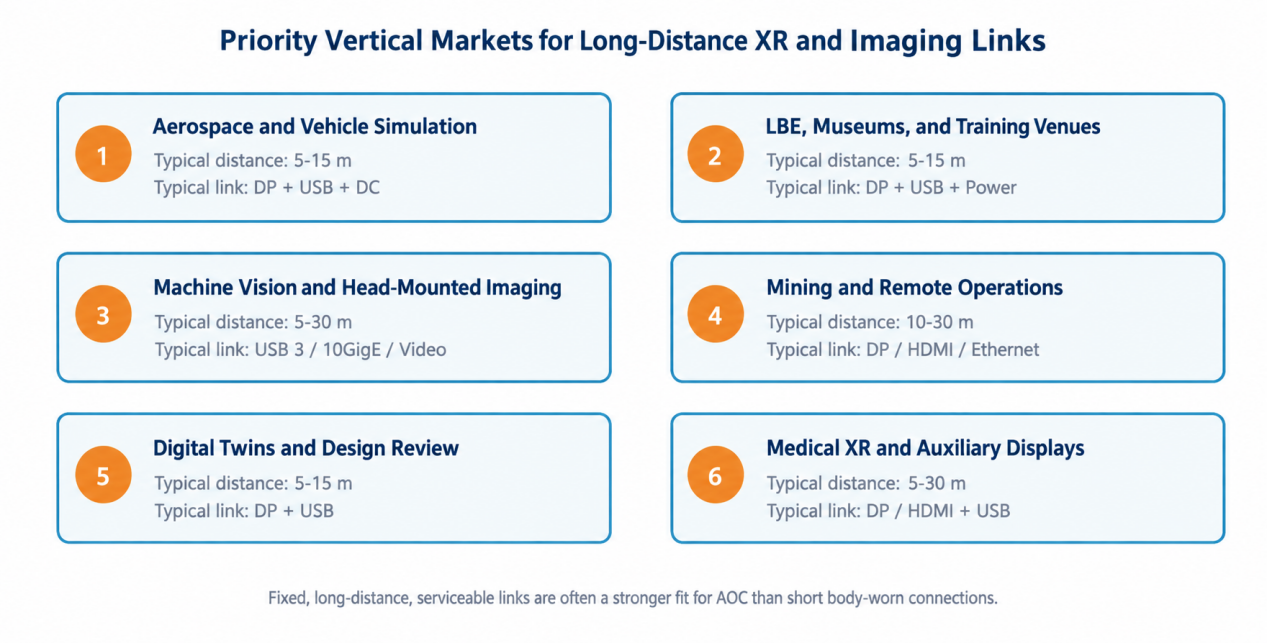
| Vertical Market | Typical Physical Link | Primary Purchasing Criteria |
|---|---|---|
| Aerospace and vehicle simulation | 5-15 m from workstation or cockpit to headset/display | Stable latency, EMI performance, reliable routing, and field replacement |
| Location-based entertainment, museums, and training venues | 5-15 m from equipment rack to multiple headsets or link boxes | High cycle life, cable management, and rapid service |
| Machine vision and head-mounted imaging | 5-30 m from camera to processing rack | Frame integrity, trigger timing, latching, and environmental robustness |
| Mining and remote operations | 10-30 m from control cabinet to display/camera | Ruggedness, serviceability, EMI performance, and dust resistance |
| Digital twins and design review | 5-15 m from GPU workstation to headset or video wall | High resolution, project-specific installation, and configuration flexibility |
| Medical XR and auxiliary displays | 5-30 m from imaging source or workstation to headset/display | Traceability, cleanability, change control, and system validation |
5. Product Platform Opportunities
| Platform | Reference Distance and Signal | Application Focus |
|---|---|---|
| P1 Hybrid AOC for PC VR | 5/6/10/15 m; DP 1.4-class video + USB 3.x + optional DC | Low drag, EMI control, integrated or split architecture, and replaceability |
| P2 USB Link AOC | 5 m; USB 3.2 Gen 1 + power-maintenance path | Right-angle device-end design and coordinated validation of streaming and charging |
| P3 Industrial simulation harness | 5/15 m; DP + USB-C cable pair or integrated cable | Latching, identification, repair, routing clamps, and industrial jacket |
| P4 AR dock extension cable | 3/5 m; HDMI, DP, or USB-C from a dock or control box | Retain copper for the short body-worn lead and extend the fixed-equipment side |
| P5 Camera and head-mounted imaging AOC | 3/5/10/30 m; project-specific USB 3, Ethernet, HDMI, or SDI | Latching, strain relief, synchronization, and separation of signal and power |
| P6 Ground-station and field AOC | 5/10/30 m; DP, HDMI, USB, or Ethernet | Control consoles, equipment enclosures, and outdoor installations |
| P7 Machine vision AOC | 5/10/15/30 m; USB3 Vision or 10GigE | Dropped-frame performance, trigger latency, thermal behavior, and bend testing |
| P8 Multi-display simulation AOC | 10/15/30 m; DP or HDMI plus project-specific control signals | Common spares, rapid replacement, and long-duration stability |
6. Hybrid Architecture and Key Design Variables
A hybrid AOC converts high-speed video or data into optical signals close to the source, carries the main transmission distance over multimode fiber, and restores the electrical interface near the destination. Copper conductors can remain in the cable for power, ground, control, hot-plug functions, or auxiliary data. Connector pin assignments, directionality, power-up sequencing, and protocol-training behavior must be defined at the project level.
| Design Domain | Issues to Resolve | Typical Validation Evidence |
|---|---|---|
| Protocol and signal integrity | Version, lane count/rate, DSC, equalization, and return loss | Eye diagrams, BER, interoperability, and margin reports |
| Optical design | Wavelength, fiber count, TX power, RX sensitivity, and bending | Optical power budget, channel consistency, and aging margin |
| Power and control | Voltage, current, voltage drop, ground, HPD/AUX/USB, and charging | Worst-case voltage, noise, timing, and fault behavior |
| Latency and recovery | Fixed or variable latency, retraining, and link dropouts | End-to-end latency, recovery time, and visible failure behavior |
| Mechanical design | Drag, flexibility, torsion, tensile load, crush, latching, and strain relief | Application-sequenced bend, torsion, and tensile testing |
| Environment and EMC | Temperature, humidity, routing, emissions, and immunity | Pre-compliance scans and customer-system validation |
| Manufacturing | End-face cleanliness, test limits, serial numbers, and change control | Control plan, final-test coverage, and lot traceability |
7. Validation Framework
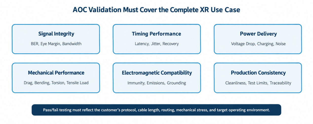
Validation should combine representative cable lengths, protocol modes, power loads, temperatures, connector configurations, and mechanical preconditioning. A scenario-based design verification plan is more valuable than isolated tests because field failures often result from interacting factors. For example, bend-induced optical loss may combine with temperature drift and insufficient receiver-sensitivity margin to produce an intermittent link.
8. Elike Capability Matrix
| Capability Area | Customization Scope | Customer Deliverable |
|---|---|---|
| Optical engine | VCSEL/PIN, driver/TIA, coupling, LDO, and compact packaging | Characterized TX/RX engine samples |
| Embedded TX/RX module | PCB, board-to-board connector, pinout, thermal path, and firmware/control | Interface control document and module prototype |
| Hybrid cable construction | Fiber, copper conductors, shielding, strength members, jacket, and strain relief | Construction proposal and mechanical samples |
| Finished AOC harness | Termination, overmolding, locking connectors, and labeling | Application-specific DVT harnesses |
| Validation support | SI/BER, optical, latency, power, EMC pre-scan, and life testing | DVP matrix, validation reports, and production-test concept |
| Production ramp | DFM, test limits, cleanliness, serial numbers, and change control | Controlled release package and traceability plan |
9. Joint Development Process
| Stage Gate | Joint Activities | Exit Evidence |
|---|---|---|
| 1 Requirements discovery | Define the physical link, endpoints, protocols, power, distance, and environment | Requirements and responsibility matrix |
| 2 Architecture design | Evaluate optical-conversion locations, cable construction, and connectors | Architecture review and preliminary risk register |
| 3 Prototype development | Build representative lengths and characterize the complete link | Prototype report and updated limits |
| 4 DVT qualification | Run SI, optical, power, EMC, and mechanical sequence testing | Validation report and issue closure |
| 5 Production release | Freeze drawings/BOM, final inspection, traceability, and change rules | Controlled production release |
10. Information Required for an Architecture Review
- Target product and installation method: headset, Link Box, simulator, camera, video wall, dock, or equipment rack.
- Source and sink interfaces, protocol versions, lane rates, compression method, refresh rate, and target display modes.
- Required distance, routing path, minimum bend radius, division between body-worn and fixed sections, and maintenance strategy.
- Power rails, current, allowable voltage drop, ground and control conductors, and charging requirements.
- Connector families, pinouts, latching, directionality, hot-plug behavior, and field-replacement requirements.
- Operating environment, EMC conditions, cleanliness requirements, life-test sequence, and acceptance criteria.
- Prototype quantity, target schedule, DVT responsibilities, expected production volume, and traceability requirements.
| Next Step Elike invites XR device manufacturers, simulation-system developers, industrial-camera companies, ODM/EMS partners, and system integrators to conduct confidential link-architecture reviews and prototype-development planning. The examples in this paper are starting points only. Compatibility, safety, regulatory compliance, and performance must be validated within the customer’s complete system. |
References
- VESA. DisplayPort 1.3 standard announcement: HBR3 at 8.1 Gbit/s per lane, 32.4 Gbit/s aggregate bandwidth, and a 25.92 Gbit/s effective data rate for uncompressed video. https://vesa.org/uncategorized/vesa-releases-displayport-1-3-standard/
- Varjo. XR-4 cable replacement instructions and accessories: replaceable 5 m and 15 m display/data cable pairs. https://support.varjo.com/hc/en-us/connecting-a-new-cable-pair-xr-4
- HTC VIVE Business. VIVE Pro 2 product information: Link Box, DisplayPort, USB 3.0, and power architecture. https://business.vive.com/uk/product/vive-pro2/
- Pimax Store. 6 m fiber-optic cable: stated maximum data rate of 32.4 Gbit/s and model-specific compatibility limitations. https://store.pimax.com/products/pimax-6m-fiber-optical-cable
- Elike VR/AR AOC customer and vertical-market workbook, updated August 22, 2026; public-source market mapping used for sales prioritization and product definition.