
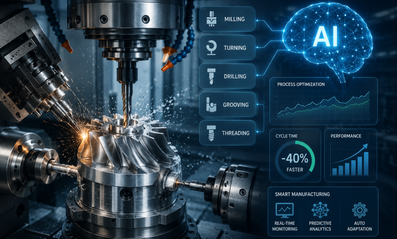
Multi-process combined machining—basically, doing turning, milling, drilling, and threading in a single setup—has been around for a while, but honestly, most shops still don’t use it right. The pain point? Fixture changes. Each re-chuck introduces positioning error, adds floor time, and burns money. Frankly, the gap between “we have a mill-turn” and “we actually cut cycle time by 40%” is almost entirely a process planning problem, not a machine capability problem. This article covers the architecture of combined machining workflows: how to sequence operations, where the real tolerance risks live, and what it takes to program Swiss-type lathes for complex multi-feature parts without losing your mind.
How Combined Machining Solves the Multi-Setup Limitation
The Fixture-Error Challenge
Every time you re-chuck a part, you’re gambling. Concentricity error between setups—typically sort of in the 0.01–0.03mm range, give or take—accumulates. For a simple bracket, fine. But for anything with cross-features that must be coaxial or perpendicular to a turned diameter, that accumulated error is basically wrong. Non-negotiable problem.
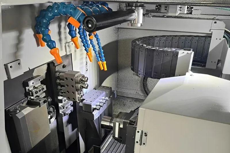
The Synchronization Mechanism
Combined machining uses live tooling spindles (rotating cutters mounted on the turret) synchronized with the main C-axis (rotational positioning of the workpiece spindle). The workpiece holds position while the mill cutter interpolates. The result? Features that reference a single datum. Always. Repeat: a single datum.
The Architectural Difference vs. Sequential Machining
Traditional sequential machining—turn on a lathe, move to a VMC, re-fixture—assumes each machine holds tolerances independently. Combined machining assumes the part never leaves the spindle until it’s done. Actually—no, not “done”—until all critical features are cut relative to each other. That’s the whole deal. One datum, one handling. Period.
Performance Specifications and Material Constraints
Achievable Tolerance Ranges
Turning tolerances on modern mill-turn centers: roughly ±0.005mm to ±0.010mm on diameter (IT5–IT6 class, per ISO 286). Milled features—slots, flats, cross-holes—hold about ±0.01–0.02mm positionally relative to the turned datum. [Important] Surface finish on turned diameters: Ra 0.4–1.6μm typically, depending on insert geometry and feed. Thread tolerances to 6H/6g class (ISO 965) are achievable in-cycle without secondary operations.
Hmm, where was I? Right—the C-axis positioning accuracy matters enormously here. Good machines hold ±0.001° on C-axis, which translates to roughly ±0.0017mm of angular position error at a 100mm radius. Practically speaking, that’s not a problem for most cross-features.
Material Suitability Matrix
Stainless works. Aluminum is lighter and machines fast—insert geometry selection matters more. Titanium—the aerospace grade stuff, not the bike hardware you see in consumer catalogs, completely different alloy regime—work-hardens if the tool rubs even briefly at Ti-6Al-4V feeds, and that ruins the day.
| Material | Machinability Index | Typical Surface Finish (Ra) | Chip Control Risk |
| 303 Stainless (ASTM A582) | 45% (free-machining) | 0.8–1.6 μm | Low |
| 6061-T6 Aluminum (AMS 2770) | 200%+ | 0.4–0.8 μm | Medium (long chips) |
| Ti-6Al-4V (AMS 4928) | 22% | 1.6–3.2 μm | High (work-hardening) |
| 4140 Alloy Steel (ASTM A29) | 65% | 0.8–1.6 μm | Medium |
| 303 Brass (ASTM B16) | 300%+ | 0.2–0.4 μm | Very Low |
Thermal Influences on Dimensional Stability
The thermal expansion thing—coefficient is roughly 11.7 for low-alloy steel (×10⁻⁶/°C per ISO 404 guidance), stainless around 16, aluminum at 23—actually forget the math for a second—it just means your dimensions drift as the machine warms up. Typically sort of 15–30 minutes of warm-up stabilizes the spindle thermally. Shops that skip warm-up cycles and then wonder why the first 20 parts are out of tolerance… yeah. Not uncommon to see that failure mode.
Geometric Boundaries
Live tooling spindle power: generally 3–7.5 kW on mid-range machines. That limits milling depth of cut. Cross-drilling is basically unlimited in terms of position, but hole diameter above roughly 20mm needs pre-drilling or interpolated helical milling—not always possible depending on turret clearance. Gear hobbing attachments are available on some platforms; that’s a separate conversation.
Design Parameters for Production Viability
DFM Guidelines for Combined Machining
Design for combined machining means—let me back up—it means designing so the part can be fully defined from a single Z-datum and a single C-axis zero. Features that require a second setup because they’re on the back face? Fine, that’s what sub-spindles are for. But features that require a completely different datum plane? That’s where you get into trouble.
Practically speaking: keep cross-features (radial holes, flats, keyways) at reasonable distances from the chuck face. Minimum 3× tool-diameter clearance from the chuck jaw is the rough rule of thumb. And honestly, avoid deep pockets that require a separate tombstone setup. Just don’t do it if combined machining is the plan.
For Swiss-type CNC lathe programming specifically—where the guide bushing (that sleeve that supports the bar stock right at the cutting zone) enables L/D ratios of 20:1 or more—the DFM rules shift. You’re designing for bar-fed production of long, slender features, not chuck work. The guide bushing thing means tolerances approach ±0.003–0.005mm on turned diameters even on long parts. [Check this] That’s the benchmark that matters for micro-medical components.
Tolerance Risk Management
The big failure modes, basically: tool runout in live spindles (check with a test indicator, not just the spec sheet—they’re not the same thing), thermal drift on first-article inspection versus production inspection, and—this one gets people—incorrect synchronization of C-axis with milling spindle speed. If the C-axis index is off even half a degree on a hex feature, you get a part that looks fine until you try to wrench it.
Wait, not quite. The real issue is that most programmers verify the angular feature visually, not with CMM or optical comparator. Scratch that approach. Verify dimensionally on first article. Always.
Economic Thresholds
Combined machining pays off above—roughly—15–20 parts per batch [Don’t quote me on the exact number], assuming manual setup on a mill-turn runs about 45–90 minutes. Below that, the setup amortization doesn’t justify the programming time. For high-volume bar-fed work (500+ pieces), the economics are obvious. It’s the 5–50 piece prototype-to-production regime where the calculation actually needs to be done, not assumed.
Applications Across Medical, Aerospace, and Fluid Power
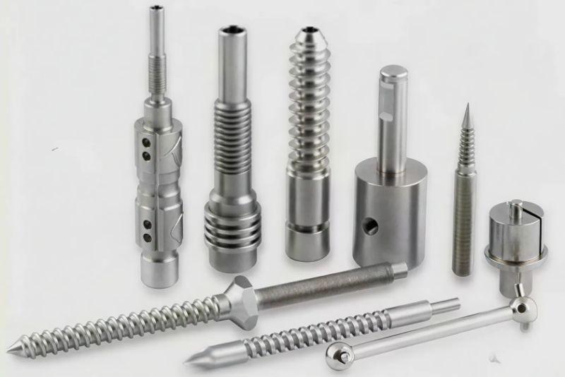
Medical Device Manufacturing
Surgical implant components—bone screws, cannulated fasteners, instrument handles—require cross-holes, flats, and threads all relative to a single axis. Tolerance requirements per ISO 13485 QMS framework, with surface finish Ra ≤ 0.8 μm on contact surfaces. Not uncommon to see 316L stainless or Ti-6Al-4V here. Single-setup combined machining eliminates the fixture-induced position error that would otherwise require 100% CMM inspection.
Aerospace Structural and Fluid Components
Hydraulic manifolds (per AS9100 Rev D quality requirements) with cross-drilled passages, NPT/SAE ports, and external mounting features. The whole deal is that positional tolerances between fluid passages—typically ±0.05mm or tighter—are only reliably achievable without re-fixturing. Plus, aerospace FAI (First Article Inspection) requirements mean every feature is documented; single-setup machining simplifies the datum traceability chain enormously.
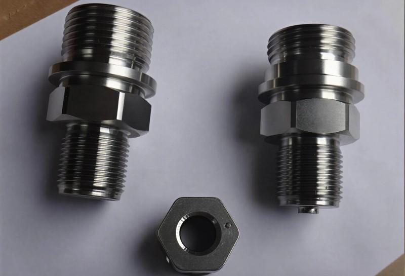
Fluid Power and Instrumentation
Valve bodies, sensor housings, precision fittings. O-ring groove concentricity to bore—sort of the critical feature here—needs better than 0.02mm TIR (Total Indicator Reading) consistently. Combined machining holds this. Sequential machining, honestly, struggles.
Process Limitations and Alternative Methods
Technical Boundaries
Combined machining on a mill-turn is not a free lunch. Deep cavity milling—anything over roughly 4× cutter diameter depth—is problematic due to live spindle rigidity limits. Part diameter above 300–400mm starts pushing machine envelope. And gear-form features? Basically out of scope without specialized attachments.
Application Exclusions
Large prismatic parts (think: anything that belongs on a horizontal machining center with a pallet changer) don’t fit the combined machining workflow. Also, grinding—cylindrical, ID, surface—is excluded; mill-turns don’t grind. Post-process grinding is still required for bearing journals and precision bores below Ra 0.2 μm.
Alternative Approaches
Transfer lines for very high volume (10,000+). Horizontal machining centers for large cubic parts. And—the relevant comparison—Swiss-type lathes for small-diameter, long-aspect-ratio parts where the guide bushing support enables the 20:1 L/D ratio that a conventional chuck setup can’t hold. Different tool for a different problem. Not competing, really. Complementary.
Conclusion
Combined machining cuts cycle time and fixture error, but only when process planning is done right. Sequence matters. Material machinability limits the tool selection. DFM rules—single datum, adequate clearances, feature geometry compatible with live tooling—are non-negotiable. And the economic threshold is real: below roughly 15 pieces, the math doesn’t always work.
The validation checkpoint most shops miss: first-article CMM verification of all cross-feature positions, not just turned diameters. Thermal stabilization before that inspection. And synchronized C-axis verification on angular features. Get those three right, and combined machining delivers what it promises. For engineers working through the full precision manufacturing capability range—Swiss CNC tolerances, ±0.005mm work, and multi-process planning—Richconn covers the capability range we’ve been discussing.